A Cmos Peak Detector Sample And Hold Circuit - In this paper, a pdsh architecture is presented which is especially designed for cmos integration.< >
A Cmos Peak Detector Sample And Hold Circuit - In this paper, a pdsh architecture is presented which is especially designed for cmos integration.< >. Effect of load on the peak detector circuit: Seems to me that a peak detector and an envelope filter are exactly the same. The desire of integrating complete particle detection systems on a single ic requires compact and low power peak detect sample and hold circuits (pdsh). A low power half wave rectifier is designed using floating current source and four. These capacitors were not present in assignment 3.
Any good reference paper for cmos peak detector that can detect the peak at 1 gbps? A low power half wave rectifier is designed using floating current source and four. This is usually necessary when the signal is asymmetrical, something which is very common with audio signals. Edaboard.com is an international electronic discussion forum focused on eda software, circuits, schematics, books, theory, papers, asic, pld, 8051, dsp, network, rf, analog design, pcb. Seems to me that a peak detector and an envelope filter are exactly the same.
Sample and Hold Settling Time - Chemistry LibreTexts from chem.libretexts.org If the peak detection is to function on both positive and negative half cycles (and they can be very different), a precision rectifier is used in front of the peak detector. The following figure shows a simple peak detector circuit using diode and capacitor. To illustrate the limitation of traditional cmos peak detector circuits, consider fig. So a circuit detecting gigahertz signals is required for a mobile bug. Effect of load on the peak detector circuit: Peak detector circuit is used to find the peak amplitude in a rapidly changing waveform. A peak detector circuit is a circuit that is able to measure the peak amplitude that occurs in a waveform. The desire of integrating complete particle detection systems on a single ic requires compact and low power peak detect sample and hold circuits (pdsh).
If the peak detection is to function on both positive and negative half cycles (and they can be very different), a precision rectifier is used in front of the peak detector.
A peak detector is a circuit which holds maximum amplitude value of a signal. In this paper, a pdsh architecture is presented which is especially designed for cmos integration.< > Effect of load on the peak detector circuit: This is achieved by peak detector circuit. Peak detectors are generally used in the sound now, in the negative half cycle of the signal, the diode gets reverse biased and at that time the capacitor holds the peak value of the previous half cycle. In the positive half cycle to avoid this select rl of very large value so that capacitor discharges very slowly hence almost holds the charge. Capacitor and, since the switch is. The diode permits the current in. It can be built simply with a diode and a capacitor. The envelope filter just uses a smaller cap or higher discharge resistor to create the you generally want your peak detector to be faster than your sample rate from the adc. So a circuit detecting gigahertz signals is required for a mobile bug. Positive and negative peak detector circuit using smp04. Tially mitigates the track and hold tradeoff discussed the input device is off, the last sampled input is stored on the load.
The sample and hold circuit samples this r peaks which set an automatic threshold for the comparator when turned on triggers a monoshot r peak detection and shaping circuit design of half wave rectifier. In this paper, a pdsh architecture is presented which is especially designed for cmos integration. Ideally, the capacitor of the peak detector should hold the peak voltage of the signal. Capacitor and, since the switch is. In this paper, a pdsh architecture is presented which is especially designed for cmos integration.< >
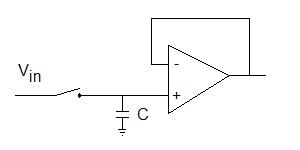
Photoconductive sampling switch consisting of an 8-finger ... from www.researchgate.net In the positive half cycle to avoid this select rl of very large value so that capacitor discharges very slowly hence almost holds the charge. The second (output) op amp is simply a buffer. A peak detector is a circuit which holds maximum amplitude value of a signal. Ideally, the capacitor of the peak detector should hold the peak voltage of the signal. It turns out that the simplest peak detector circuit can be built without the need for any complex components such as chips; Positive and negative peak detector circuit using smp04. Seems to me that a peak detector and an envelope filter are exactly the same. Any good reference paper for cmos peak detector that can detect the peak at 1 gbps?
And add peak resetting feature.
The desire of integrating complete particle detection systems on a single ic requires compact and low power peak detect sample and hold circuits (pdsh). Peak detectors are generally used in the sound now, in the negative half cycle of the signal, the diode gets reverse biased and at that time the capacitor holds the peak value of the previous half cycle. Any good reference paper for cmos peak detector that can detect the peak at 1 gbps? Please write adc analog to digital controller converter, not atd. In this paper, a pdsh architecture is presented which is especially designed for cmos integration.< > Positive and negative peak detector circuit using smp04. In the positive half cycle to avoid this select rl of very large value so that capacitor discharges very slowly hence almost holds the charge. Where cpara is the parasitic capacitance 1. As it is a positive peak detector, one can also construct a negative. Peak detector detects and holds the most positive value of attained by the input signal prior to the time when the switch is closed. If the peak detection is to function on both positive and negative half cycles (and they can be very different), a precision rectifier is used in front of the peak detector. This is usually necessary when the signal is asymmetrical, something which is very common with audio signals. It stores the peak value of input voltages for infinite time thereby allowing the capacitor to hold the value of the previously occurred peak.
Peak detector circuit is used to find the peak amplitude in a rapidly changing waveform. Positive and negative peak detector circuit using smp04. A cmos clock recovery circuit for 2. The sample and hold circuit samples this r peaks which set an automatic threshold for the comparator when turned on triggers a monoshot r peak detection and shaping circuit design of half wave rectifier. The diode permits the current in.
Figure 3. All-digital polar transmitter: (a) block diagram ... from www.researchgate.net So a circuit detecting gigahertz signals is required for a mobile bug. If a signal varies rapidly and we are unable to measure it, then we go for here, we are going to see simple peak detector circuit that consists of one diode, one capacitor and one resistor. The error introduced by clock feedthrough is usually very small compare to. It turns out that the simplest peak detector circuit can be built without the need for any complex components such as chips; In this paper, a pdsh architecture is presented which is especially designed for cmos integration.< > Ideally, the capacitor of the peak detector should hold the peak voltage of the signal. A peak detector circuit is a circuit that is able to measure the peak amplitude that occurs in a waveform. 67 216 просмотров 67 тыс.
Ideally, the capacitor of the peak detector should hold the peak voltage of the signal.
The desire of integrating complete particle detection systems on a single ic requires compact and low power peak detect sample and hold circuits (pdsh). These capacitors were not present in assignment 3. Seems to me that a peak detector and an envelope filter are exactly the same. Please write adc analog to digital controller converter, not atd. Positive and negative peak detector circuit using smp04. The desire of integrating complete particle detection systems on a single ic requires compact and low power peak detect sample and hold circuits (pdsh). The error introduced by clock feedthrough is usually very small compare to. A cmos clock recovery circuit for 2. It stores the peak value of input voltages for infinite time thereby allowing the capacitor to hold the value of the previously occurred peak. Ideally, the capacitor of the peak detector should hold the peak voltage of the signal. Peak detector circuit is used to find the peak amplitude in a rapidly changing waveform. It can be built simply with a diode and a capacitor. 67 216 просмотров 67 тыс.
Related : A Cmos Peak Detector Sample And Hold Circuit - In this paper, a pdsh architecture is presented which is especially designed for cmos integration.< >.